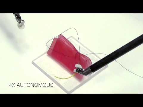
Autonomous Surgical Suturing

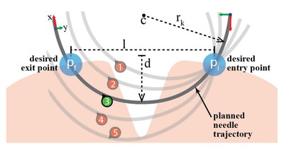
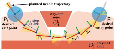
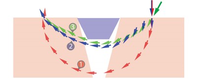
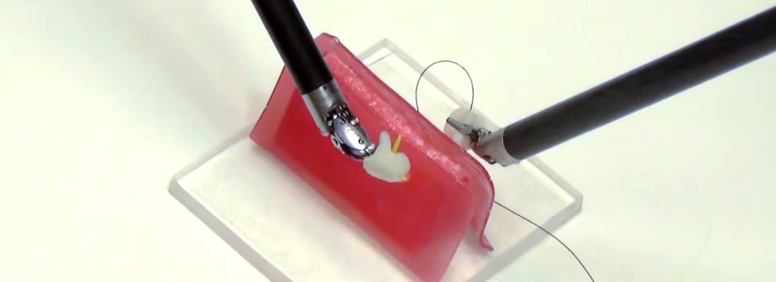
Automating Multi-Throw Multilateral Surgial Suturing with a Mechanical Needle Guide and Sequential Convex Optimization

Robotic Surgical Assistants (RSA)

fullscreen fullscreen_mobile
Fig. 1: The figure outlines the Multi-Throw Suturing Finite State Machine. First the surgeon specifies a suture path with wound width & depth and suture pitch. The system then computes the number of suture throws required; and generates entry & exit points, and optimized trajectories along with required needle size for each throw of the MTS. Each of the steps S1-S5 (see Figure 1) are repeated with visual feedback for each suture throw until all suture throws are completed.

play 
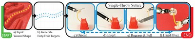
Autonomous Multi-Throw Multilateral Surgical Suturing

fullscreen fullscreen_mobile
Fig. 2: The needle trajectory labeled (3) shows the desired trajectory along with poses at entry and exit points from the tissue. The success of suturing depends on correct orientation of needle with respect to the tissue. For example, uncertainty in needle pose at entry point may result in the needle not connecting opposite tissue sides (1), not making sufficiently deep insertion to hold the suture securely (2), not having enough length of needle at the other end to enable re-grasping (4), or passing completely under the wound and not exiting the tissue at all (5).
fullscreen fullscreen_mobile
Fig. 3: The optimization steps and non-holonomic motion at each time-step. The figure shows stay-out zones $\mathcal O_i$, trajectory poses $X_t$, step-size $\delta$, needle radius $r$, and $\gamma$-cone of allowed rotation at each $X_t$.
fullscreen fullscreen_mobile
Fig. 4: The side view of three needle trajectories generated by SPP. Trajectory 1 and 3 are constant curvature trajectories whereas trajectory 2 is a variable curvature trajectory.
fullscreen fullscreen_mobile
Fig. 5: This figure illustrates the design and function of the 3D-printed Suture Needle Angular Positioner (SNAP). Figures (a) and (b) show a convex depression in which needle rests upon gripper closure. Figure (d) shows a time-lapse figure of the gripper closing action on needle orientation
fullscreen fullscreen_mobile
Fig. 6: This figure shows an overview of the needle tracking pipeline, from stereo images to the final needle pose estimate overlaid onto the original scene. We fuse a Kalman Filter estimate with current camera estimate to compute the final estimate. The tracking system is robust to outliers and missing data in the segmentation masks
fullscreen fullscreen_mobile
TABLE I: Error in Relative Needle Pose (Over 20 Trials)
fullscreen fullscreen_mobile
TABLE II: SNAP Evaluation